LILYGO T-Display ESP32 (1.14 inch LCD): specs and pinout
An ESP32 board from LilyGO with a 1.14 inch IPS colour screen (ST7789V), USB-C and two buttons.
Specs
| Spec | Value | Source |
|---|---|---|
| Display controller | ST7789 (ST7789V) | source README Pinout table (TFT Driver); pinmap image caption |
| Display size | 1.14 inch IPS | source pinmap.jpg caption |
| Arduino IDE settings (maker) | Board ESP32 Dev Module, PSRAM disabled, Flash Size 4MB | source README Quick start step 4 |
| TFT_eSPI library limit | Maker says TFT_eSPI is supported up to version 2.0.14; newer versions give a compile error | source README Quick start step 7 |
| Supply voltage (ESP32 chip) | 2.3 V / 3.0 V min, 3.3 V typ, 3.6 V max | source Table 5-2 (p.51) |
| Pin source / sink current (ESP32 chip) | 40 mA / 28 mA typ per pin at 3.3 V | source Table 5-3 (p.52) |
| Input high level VIH (ESP32 chip) | 0.75 x VDD min, VDD + 0.3 V max | source Table 5-3 (p.52) |
| Wireless | 2.4 GHz Wi-Fi (802.11 b/g/n) and Bluetooth v4.2 BR/EDR + BLE (ESP32 chip) | source Cover page and features (p.1, p.3) |
Power
| Value | Source | |
|---|---|---|
| Supply | USB-C or the 5V pin; the ESP32 chip itself runs at 3.3 V | source pinmap.jpg (5V and 3V3 pins) |
Pinout
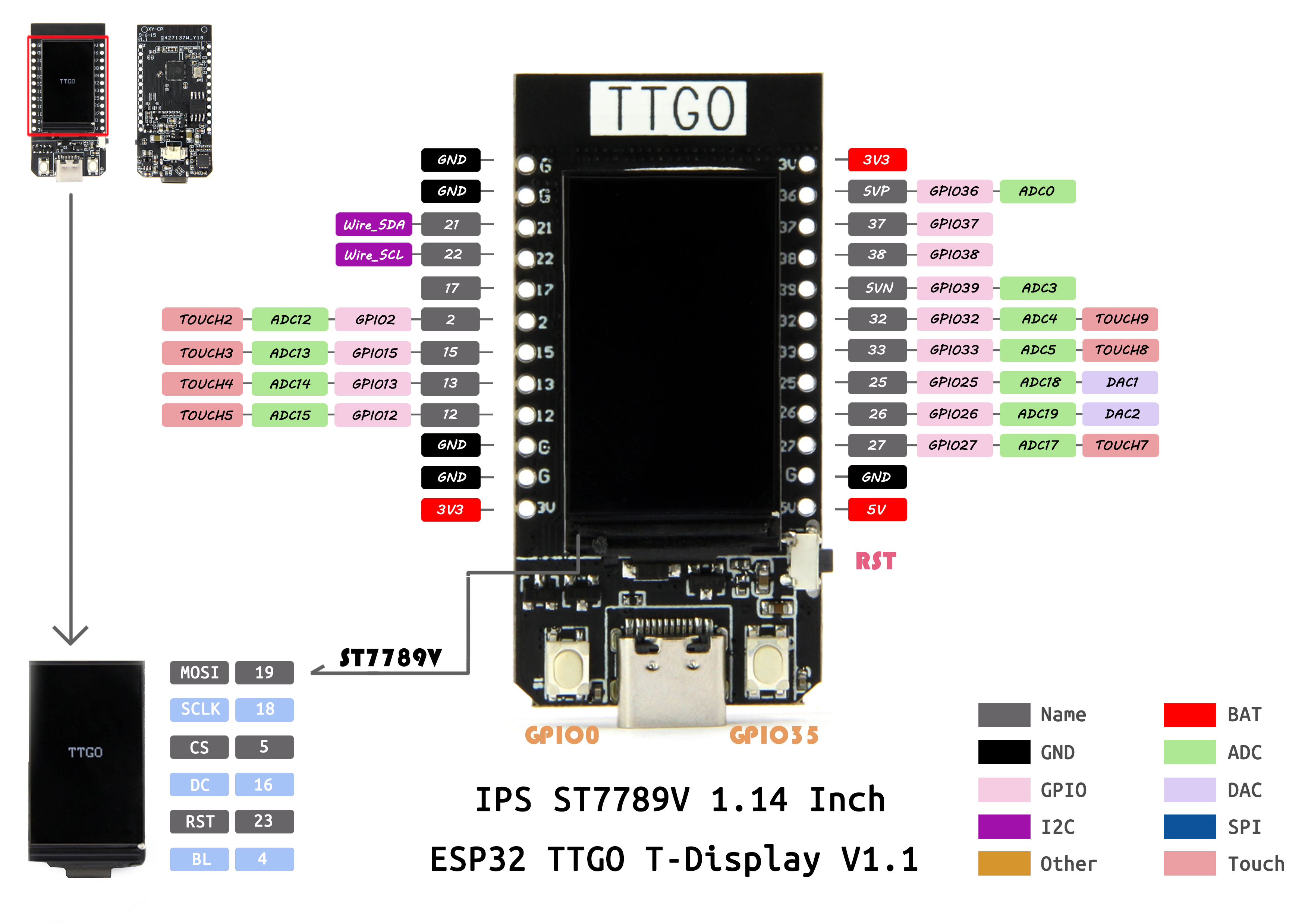
Pin names are copied from the maker pinmap image (T-Display V1.1) and README. If your board revision differs, check the silkscreen.
| Pin | Function | Voltage | Notes | Source |
|---|---|---|---|---|
| GND | GND | left header, position 1 from the top (USB at the bottom, screen facing you) | source image/pinmap.jpg, ESP32 TTGO T-Display V1.1 | |
| GND | GND | left header, position 2 from the top (USB at the bottom, screen facing you) | source image/pinmap.jpg, ESP32 TTGO T-Display V1.1 | |
| 21 | GPIO21, Wire_SDA (I2C) | left header, position 3 from the top (USB at the bottom, screen facing you) | source image/pinmap.jpg, ESP32 TTGO T-Display V1.1 | |
| 22 | GPIO22, Wire_SCL (I2C) | left header, position 4 from the top (USB at the bottom, screen facing you) | source image/pinmap.jpg, ESP32 TTGO T-Display V1.1 | |
| 17 | GPIO17 | left header, position 5 from the top (USB at the bottom, screen facing you) | source image/pinmap.jpg, ESP32 TTGO T-Display V1.1 | |
| 2 | GPIO02, ADC12, TOUCH2 | left header, position 6 from the top (USB at the bottom, screen facing you) | source image/pinmap.jpg, ESP32 TTGO T-Display V1.1 | |
| 15 | GPIO15, ADC13, TOUCH3 | left header, position 7 from the top (USB at the bottom, screen facing you) | source image/pinmap.jpg, ESP32 TTGO T-Display V1.1 | |
| 13 | GPIO13, ADC14, TOUCH4 | left header, position 8 from the top (USB at the bottom, screen facing you) | source image/pinmap.jpg, ESP32 TTGO T-Display V1.1 | |
| 12 | GPIO12, ADC15, TOUCH5 | left header, position 9 from the top (USB at the bottom, screen facing you) | source image/pinmap.jpg, ESP32 TTGO T-Display V1.1 | |
| GND | GND | left header, position 10 from the top (USB at the bottom, screen facing you) | source image/pinmap.jpg, ESP32 TTGO T-Display V1.1 | |
| GND | GND | left header, position 11 from the top (USB at the bottom, screen facing you) | source image/pinmap.jpg, ESP32 TTGO T-Display V1.1 | |
| 3V3 | 3V3 | 3.3 V | left header, position 12 from the top (USB at the bottom, screen facing you) | source image/pinmap.jpg, ESP32 TTGO T-Display V1.1 |
| 3V3 | 3V3 | 3.3 V | right header, position 1 from the top (USB at the bottom, screen facing you) | source image/pinmap.jpg, ESP32 TTGO T-Display V1.1 |
| 36 | GPIO36, SVP, ADC0 | right header, position 2 from the top (USB at the bottom, screen facing you); Input-only on the ESP32 chip | source image/pinmap.jpg, ESP32 TTGO T-Display V1.1 | |
| 37 | GPIO37 | right header, position 3 from the top (USB at the bottom, screen facing you); Input-only on the ESP32 chip | source image/pinmap.jpg, ESP32 TTGO T-Display V1.1 | |
| 38 | GPIO38 | right header, position 4 from the top (USB at the bottom, screen facing you); Input-only on the ESP32 chip | source image/pinmap.jpg, ESP32 TTGO T-Display V1.1 | |
| 39 | GPIO39, SVN, ADC3 | right header, position 5 from the top (USB at the bottom, screen facing you); Input-only on the ESP32 chip | source image/pinmap.jpg, ESP32 TTGO T-Display V1.1 | |
| 32 | GPIO32, ADC4, TOUCH9 | right header, position 6 from the top (USB at the bottom, screen facing you) | source image/pinmap.jpg, ESP32 TTGO T-Display V1.1 | |
| 33 | GPIO33, ADC5, TOUCH8 | right header, position 7 from the top (USB at the bottom, screen facing you) | source image/pinmap.jpg, ESP32 TTGO T-Display V1.1 | |
| 25 | GPIO25, ADC18, DAC1 | right header, position 8 from the top (USB at the bottom, screen facing you) | source image/pinmap.jpg, ESP32 TTGO T-Display V1.1 | |
| 26 | GPIO26, ADC19, DAC2 | right header, position 9 from the top (USB at the bottom, screen facing you) | source image/pinmap.jpg, ESP32 TTGO T-Display V1.1 | |
| 27 | GPIO27, ADC17, TOUCH7 | right header, position 10 from the top (USB at the bottom, screen facing you) | source image/pinmap.jpg, ESP32 TTGO T-Display V1.1 | |
| GND | GND | right header, position 11 from the top (USB at the bottom, screen facing you) | source image/pinmap.jpg, ESP32 TTGO T-Display V1.1 | |
| 5V | 5V | 5 V | right header, position 12 from the top (USB at the bottom, screen facing you) | source image/pinmap.jpg, ESP32 TTGO T-Display V1.1 |
| TFT MOSI | GPIO19 | On-board ST7789V display wiring, not for other use | source README Pinout table | |
| TFT SCLK | GPIO18 | On-board ST7789V display wiring, not for other use | source README Pinout table | |
| TFT CS | GPIO5 | On-board ST7789V display wiring, not for other use | source README Pinout table | |
| TFT DC | GPIO16 | On-board ST7789V display wiring, not for other use | source README Pinout table | |
| TFT RST | GPIO23 | On-board ST7789V display wiring, not for other use | source README Pinout table | |
| TFT backlight | GPIO4 | On-board ST7789V display wiring, not for other use | source README Pinout table | |
| Button 1 | GPIO35 | On-board button; GPIO35 is input-only | source README Pinout table (BUTTON1) | |
| Button 2 | GPIO0 | On-board button (boot pin) | source README Pinout table (BUTTON2) | |
| ADC_IN | GPIO34 | README names it ADC_IN | source README Pinout table | |
| ADC Power | GPIO14 | README names it ADC Power | source README Pinout table |
Build with it
Project ideas for the LILYGO T-Display ESP32 (1.14 inch LCD). Each link opens Soldr with the prompt filled in; Soldr assigns the pins, checks power and shows how to wire every part.
- Pocket light meter: Reads the module on an ADC pin (GPIO36 or similar) and shows the value on the built-in screen; keep the output at or below 3.3 V.
- Desk clock: The DS3231 uses I2C on GPIO21 and GPIO22, which the pinmap shows as Wire_SDA and Wire_SCL.
- Temperature readout: One free GPIO carries the probe data and the screen shows the value.
Common mistakes
- GPIO0, 4, 5, 16, 18, 19 and 23 are used by the screen and buttons; do not reuse them (source: link, README Pinout table).
- Compile with TFT_eSPI 2.0.14 or older and ESP32 core 2.0.14; the maker says newer versions give a compile error (source: link, Quick start step 7).
- GPIO34, 35, 36, 37, 38 and 39 are input-only on the ESP32 chip (source: link, Table 2-1, p.14).
Not covered by the official source
- Current draw and USB power limits are not in the README.
- Pin facts come from the maker's README and pinmap image; the schematic is not reproduced here.