8 November 2026 · Soldr
SH1106 vs SSD1306: why your 1.3 inch OLED shows garbage
Short answer: most 0.96 inch OLEDs use an SSD1306 controller; many 1.3 inch ones use an SH1106. They share I2C addresses (0x3C or 0x3D) and look identical on the bus, but the SH1106 has 132 columns of memory instead of 128. Drive an SH1106 with SSD1306 code and you get a shifted image, a stripe of noise down one edge, or a scrambled screen. Use a library or driver made for the SH1106.
It's one of the most common "my screen doesn't work" questions, and the wiring is usually fine. The board found the display, the display took the commands, and the picture still came out wrong. The cause is in the controller datasheets, which we've cited on our reference pages for the SSD1306 and the SH1106.
What's the same
- I2C address. Both answer at
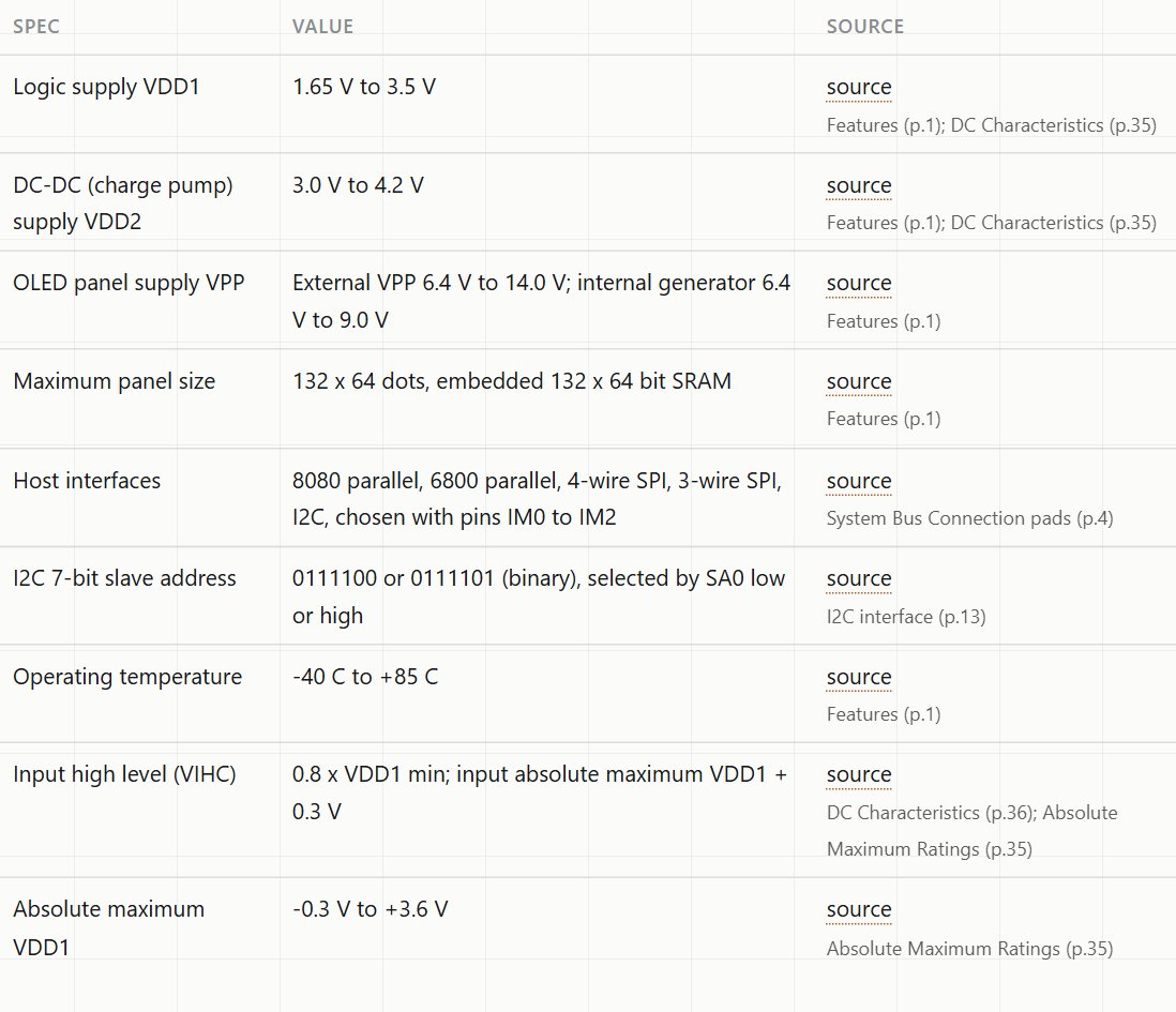
0111100or0111101in binary, selected by an SA0 pin: that's 0x3C or 0x3D. An I2C scanner can't tell them apart. - Interfaces. Both support I2C and SPI. Most small modules come wired for one or the other.
- Logic supply. The SSD1306's logic supply is 1.65 to 3.3 V; the SH1106's is 1.65 to 3.5 V, with an absolute maximum of 3.6 V. Neither chip takes 5 V on its logic supply. Modules that advertise 3.3 to 5 V do so through a regulator on the module, which neither datasheet covers.
What's different: 128 vs 132 columns
The SSD1306 drives a 128 × 64 panel with matching memory. The SH1106 datasheet gives an embedded 132 × 64 bit display RAM, for panels up to 132 dots wide.
A 1.3 inch module usually has a 128-pixel-wide glass panel on that 132-column memory. So the visible pixels sit inside the memory with a few spare columns. Code written for the SSD1306 assumes the first column of memory is the first pixel on screen. On an SH1106 it isn't, and the two controllers also handle addressing modes differently, so SSD1306 code can leave the picture offset, wrapped, or broken into stripes.
How far to offset isn't in the SH1106 datasheet, because it depends on how the module maker placed the panel. Our reference page lists that under Not covered by the official source. In practice, SH1106 drivers handle it with a small column offset; if your image sits a couple of pixels off one edge, that offset is the setting to adjust.
Wiring either one over I2C
The 4-pin I2C modules wire the same way whichever controller they carry:
- GND to the board's ground.
- VCC to the supply the module's label asks for. On a 3.3 V board like the ESP32, 3.3 V keeps the module's I2C pull-ups at the ESP32's logic level.
- SDA and SCL to the board's I2C pins: A4 and A5 on an Uno, usually GPIO21 and GPIO22 on an ESP32 DevKit.
Two OLEDs on one bus need different addresses, one at 0x3C and one at 0x3D, set with the SA0 option on the module if it has one. Otherwise, a multiplexer keeps them apart.
How to tell which one you have
- Size is a hint, not proof. 0.96 inch modules are usually SSD1306. 1.3 inch modules are often SH1106, but SSD1306 versions exist.
- Check the listing or the module's marking. Compoden lists the controller in the product name for both our 0.96 inch SSD1306 and our 1.3 inch SH1106 modules.
- Test it. If the scanner finds the display at 0x3C but SSD1306 code shows noise down one edge, it's almost certainly an SH1106.
If the screen stays blank
That's a different problem from a garbled picture. Work through it in order:
- Is it found? Run an I2C scanner. No reply at 0x3C or 0x3D means wiring or power. See I2C address conflicts for a scanner sketch.
- Is the address right in the code? Some modules are set to 0x3D. The SA0 setting decides it.
- Is it powered correctly? Follow the module's own label for VCC; the chip itself is a 3.3 V part.
- Is it the right controller in the code? SSD1306 code on an SH1106 often shows something, but not always.
A self-test at startup turns most of these into one line. The sketches Soldr writes print, for example, [INIT] SSD1306 OLED: FAIL (no ACK at 0x3C) with a fix line naming the wires, the power pin and the address to check. More on those lines.
Which to choose
- 0.96 inch SSD1306: the most common, with the widest library support. A good default for small readouts.
- 1.3 inch SH1106: bigger and easier to read across a desk. Just make sure the code targets the SH1106.
When you describe a build on Soldr, name the controller as well as the size ("a 1.3 inch SH1106 OLED"), so the build doesn't have to guess. Then check the #include lines at the top of the sketch: they show which display library the code uses. If you're unsure which controller you have, ask first: "is a 1.3 inch OLED usually SH1106?"
Describe your build on app.soldr.ai. Sign in and get 100 credits free.