8 November 2026 · Soldr
I2C address conflict: two sensors, one address, and how to fix it
Short answer: every device on an I2C bus needs its own 7-bit address. Look up each part's address in its datasheet, then fix a clash with the part's address pin (for example, tie the MPU6050's AD0 pin high to move it from 0x68 to 0x69). If a part has only one address, put the clashing parts behind a TCA9548A multiplexer. Run an I2C scanner before you trust any of it.
I2C lets two wires carry a whole row of sensors and screens. That convenience has one rule: the board calls each device by its address, and two devices with the same address answer at the same time. The result is garbage readings, a frozen bus, or a sensor that "isn't found" even though it's wired correctly. Here's how to spot a clash before you flash, and how to fix one when you hit it.
A clash you can hit with two common parts
The MPU6050 motion sensor and the DS3231 real-time clock are both popular, and both default to the same address. From their datasheets:
- MPU6050:
1101000with AD0 low,1101001with AD0 high. That's 0x68 or 0x69. - DS3231:
1101000. That's 0x68, and it has no pin to change it.
Put both on one bus with the MPU6050's AD0 left low and they collide at 0x68. The fix is on the MPU6050's side: tie AD0 to 3.3 V so it answers at 0x69, and tell your code to use 0x69. The DS3231 stays at 0x68.
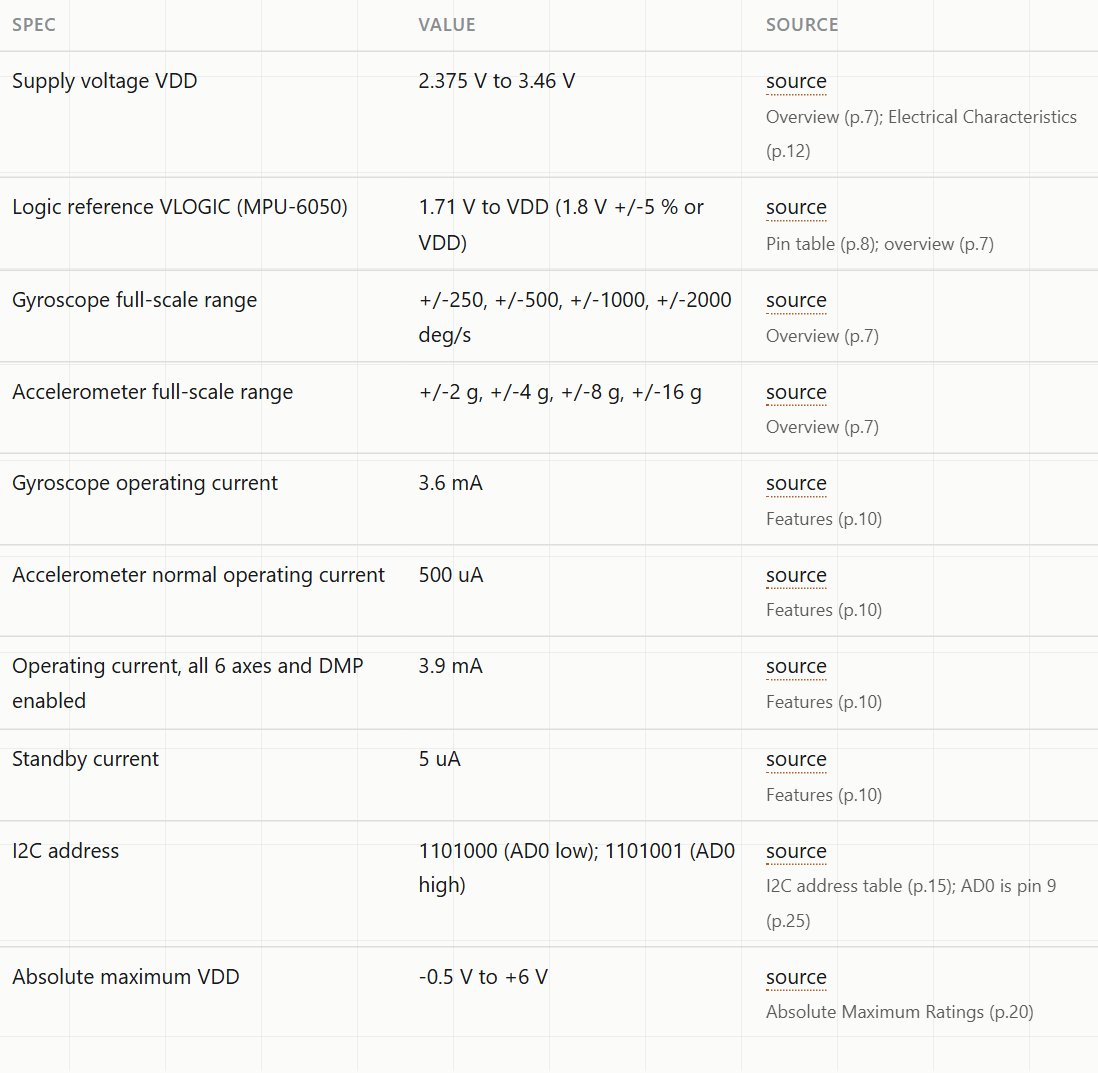
The address row on our MPU6050 reference page cites the datasheet table it came from. That matters because addresses are exactly the kind of detail that gets copied wrong between tutorials.
Addresses of parts people often combine
All of these are 7-bit addresses taken from the manufacturer's datasheet. Each link goes to a reference page that cites the section.
- SSD1306 OLED: 0x3C or 0x3D, set by the SA0 pin. Many modules ship at 0x3C.
- BME280: 0x76 with SDO to GND, 0x77 with SDO to VDDIO. The datasheet says SDO can't be left floating.
- SHT30: 0x44 with ADDR low, 0x45 with ADDR high.
- AHT10: 0x38.
- TCA9548A multiplexer: 0x70 to 0x77, set by A0, A1 and A2.
Two of the same sensor follow the same logic. Two BME280s work on one bus if one has SDO to GND (0x76) and the other to VDDIO (0x77). A third one doesn't fit, because the chip only has two addresses.
One caution about modules. The chip datasheet gives the chip's address pins; the module board decides whether that pin is brought out to the header and what it's pulled to. If your module has an AD0, ADDR or SDO pin on the header, you can set it. If it doesn't, check the module's own labels before you assume an address.
When a part has only one address: use a multiplexer
A TCA9548A sits between the board and up to eight I2C branches. Your code tells it which branch to open, then talks to the sensor on that branch as usual. Two parts with the same fixed address can each live on their own branch, and the multiplexer itself sits at its own address (0x70 by default). It costs one extra part and a few lines of code, and it's the clean answer when address pins run out.
Check the bus with an I2C scanner
Before you debug anything else, find out what's actually answering. This short sketch tries every address and prints the ones that reply:
#include <Wire.h>

void setup() {
  Serial.begin(115200);
  Wire.begin();   // on an ESP32 DevKit you can write Wire.begin(21, 22);
  for (uint8_t addr = 1; addr < 127; addr++) {
    Wire.beginTransmission(addr);
    if (Wire.endTransmission() == 0) {
      Serial.print("Found device at 0x");
      if (addr < 16) Serial.print('0');
      Serial.println(addr, HEX);
    }
  }
}

void loop() {}
You want one line per device, at the address you expected. One line where you expected two usually means a clash (or one device not powered). No lines at all usually means wiring: SDA and SCL swapped, no common ground, or no pull-up resistors on the bus.
How Soldr handles addresses
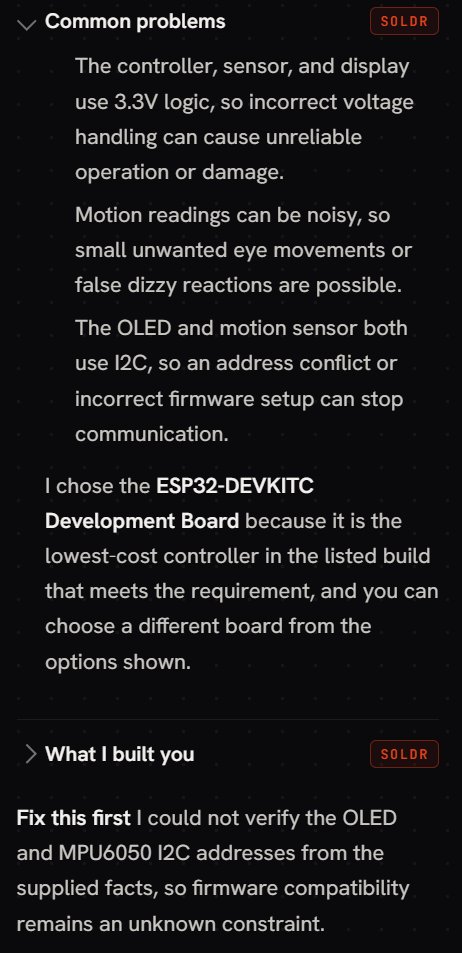
We built a motion-reactive desk buddy twice on Soldr: an ESP32, an MPU6050 and a 0.96 inch OLED on one I2C bus. The first prompt didn't mention addresses. Soldr didn't guess. It answered with a line headed Fix this first:
The second prompt said it outright: an MPU6050 at I2C address 0x68 and a 0.96 inch SSD1306 OLED at 0x3C, both on one I2C bus. That build went through, and the sketch it wrote records the addresses in its first lines:
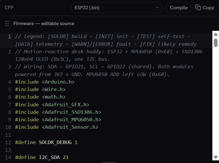
The sketch also checks each address when the board starts. If the screen doesn't answer, the Serial Monitor shows [INIT] SSD1306 OLED: FAIL (no ACK at 0x3C) followed by [FIX] SSD1306 OLED: check SDA=21/SCL=22 wiring, 3V3 power, and that the module address is 0x3C (not 0x3D). That turns "the screen is blank" into a specific thing to check. More on those lines in reading the self-test lines.
The lesson from those two runs is simple: when you know the addresses, put them in the prompt. Soldr can then check them against each other instead of flagging them.
A quick checklist
- Write down every I2C part and its address from the datasheet, not from a forum post.
- Two parts on one address? Move one with its address pin, or use a TCA9548A.
- Never leave an address pin floating. Tie it to ground or to the logic supply.
- Check the module's header: the chip may have an address pin the module doesn't expose.
- Run the scanner and match what answers to your list before you debug code.
Parts from this post on Compoden: MPU6050 module, DS3231 RTC module, TCA9548A multiplexer. For choosing pins in general, see how to choose which pin to use.
Want Soldr to check a build like this? Describe it on app.soldr.ai, with the addresses if you know them. Sign in and get 100 credits free.