Docs / Screens & dashboards
How do you design exactly what your display shows — without writing the draw code yourself?
Your build reads a sensor, but you want a specific layout on screen — a live temperature number here, a humidity bar there, a WiFi icon in the corner — not a generic dump of numbers. Hand-placing text and icons at exact pixel coordinates, then keeping the code in sync every time you move something, is exactly the kind of busywork this is meant to remove.
Where to find it
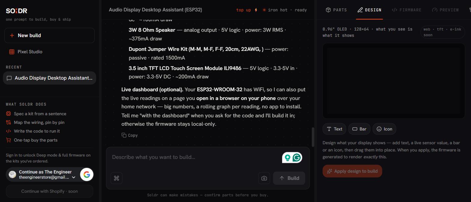
In the app it's called the Design tab, not "Screen layout" — that's the plainer name for what it does. It shows up on the tab bar (Parts, Design, Firmware, Wiring) once your build already has a display in it — the tab is display-gated, so add your OLED to the tray first if you haven't.
Not the same thing as Pixel Studio
They sound similar and solve different problems. Pixel Studio draws a single icon or animation — a static asset you export as bytes. The Design tab composes a live layout for a display already in your build — text, bars and icons tied to your actual sensor readings, applied straight to that build's firmware.
Building the layout
-
Add an element
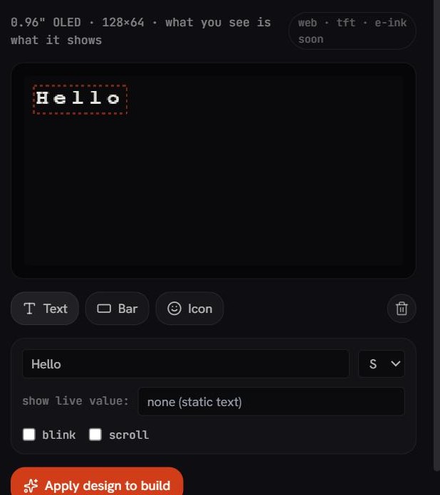
Three kinds: Text, Bar, Icon. Icons are a fixed small set (thermometer, droplet, WiFi, bell, bolt, checkmark) — enough for the common readouts without needing to design your own.
-
Drag it into place
Position snaps to the display's own pixel grid, so what you place is exactly where it lands — no rounding surprises between the editor and the real screen.
-
Bind it to a live reading
Type a key like
temp,hum,dist,soilorlight— the editor suggests keys based on the actual sensors already in your build, so you're not guessing at a name that doesn't match anything. The preview shows placeholder numbers; the real readings appear once the firmware is on the board. -
Style it
Text has three sizes and an optional scrolling marquee for anything too wide to fit. Any element can blink. There's no layers panel or alignment guide — elements can overlap, and whichever you added last sits on top.
-
Apply design to build
This saves the layout to your build — it does not generate firmware by itself. The next time you ask for the code, this exact layout gets built in.
Why the drawing code is deterministic, not guessed
Applying doesn't hand your layout to a model and hope it draws it correctly. The exact pixel positions you placed are compiled into a drawing function directly — the model's only job on the next generation is wiring up the sensor reads that feed it. The picture you designed is the picture you get, not an AI's approximation of it.
A worked example
Take a build with an ESP32 and a 0.96″ OLED (128×64, SSD1306) already carded — the exact preset this editor targets today. Open Design, add a Text element bound to temp in the top-left, a Bar element bound to hum along the bottom edge, and a WiFi icon in the top-right corner if the board has WiFi. Apply, then ask for the code — the generation that comes back draws precisely that layout, not a generic three-line dashboard template.
| Part | Why it's there | Price |
|---|---|---|
| ESP32-DevKitC (Black) | the controller, drives the OLED and (if used) WiFi | ₹340 |
| 0.96″ OLED 128×64, I2C (SSD1306) | the display the Design tab targets in v1 | ₹259 |
| Core of the example | the layout work happens in the browser, not on the board | ₹599 |
If it still doesn't look right
- v1 targets one display: a 128×64 SSD1306 OLED. Other displays (web, TFT, e-ink) show in the panel as "soon" — not yet available to design against.
- If your build's display isn't showing the Design tab at all, check that a display part is actually in the tray — the tab only appears once one is.
- Elements can overlap with no warning — if something looks hidden, check whether a later element was placed on top of it.
- Applied a design but the firmware still looks like the old layout? Applying only saves it — you need to ask for the code again afterward for it to take effect.
- Still stuck? Describe what you see versus what you designed — that's a question, not a generation, so it's free.