8 November 2026 · Soldr
NodeMCU ESP8266 won't boot? Check D3, D4 and D8
Short answer: the ESP8266 reads three pins at reset to decide how to start. To boot your sketch from flash it needs GPIO15 (D8) low, GPIO0 (D3) high and GPIO2 (D4) high. A sensor, button, relay board or LED circuit that pulls one of those the wrong way stops the board from booting. Move that part to D1, D2, D5, D6 or D7.
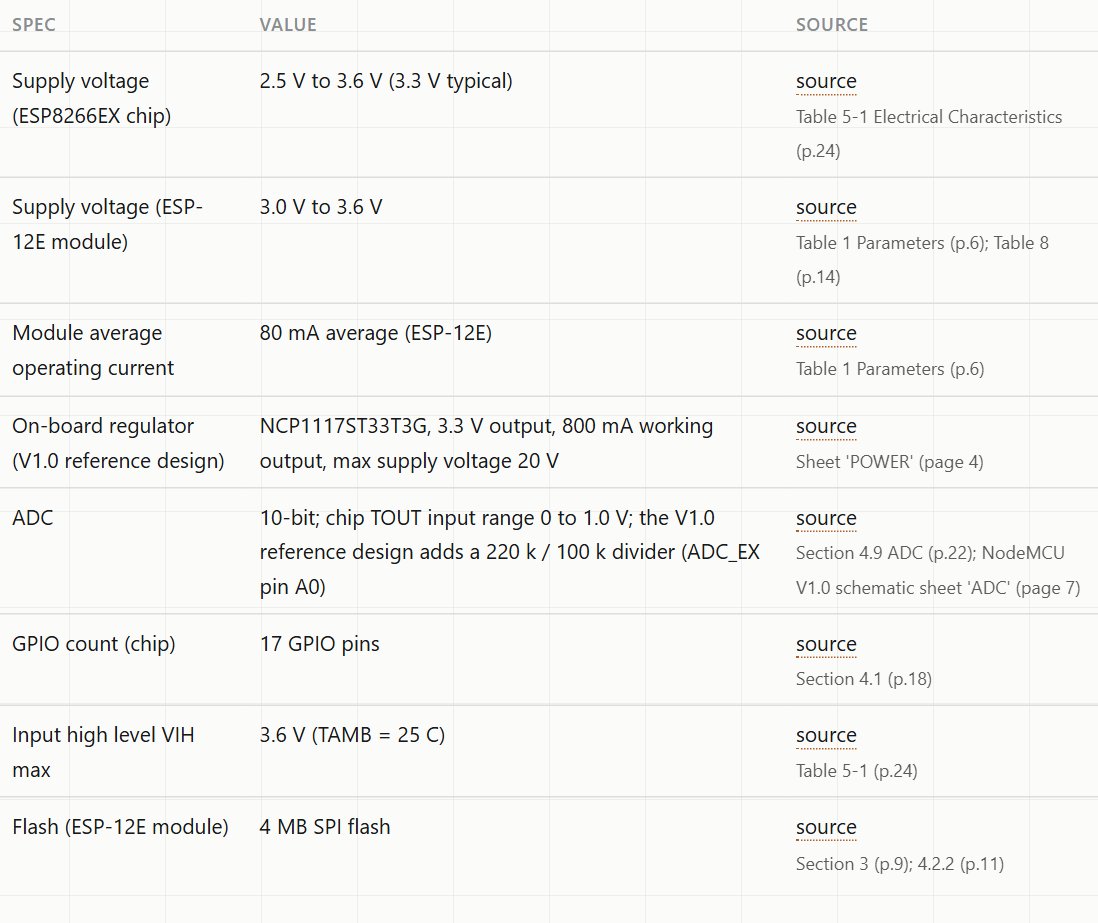
On a NodeMCU board the pins are labelled D0 to D8, which hides the fact that three of them are boot pins. The rule comes from the ESP-12E module's datasheet, which our NodeMCU ESP8266 and ESP-12E reference pages cite, along with the NodeMCU V1.0 reference schematic that maps D-numbers to GPIOs.
The boot rule
From the ESP-12E sheet:
- Flash boot (normal start): GPIO15 low, GPIO0 high, GPIO2 high.
- UART download (waiting for an upload): GPIO15 low, GPIO0 low, GPIO2 high.
And from the NodeMCU V1.0 pin map:
- D3 = GPIO0
- D4 = GPIO2 (also TXD1)
- D8 = GPIO15
What goes wrong, pin by pin
- D8 (GPIO15) pulled high at reset: the board doesn't start from flash. Typical cause: a module with a pull-up resistor on its output, or an SPI device's chip-select line.
- D3 (GPIO0) held low at reset: the board waits for an upload instead of running your sketch. Typical cause: a button to ground on D3, pressed (or wired wrong) at power-up.
- D4 (GPIO2) held low at reset: the board fails to start properly. Typical cause: a part that pulls its line low, or an LED circuit that loads the pin. Many NodeMCU boards also have an on-board LED on GPIO2, so it lights when you drive D4 low in code. That part is normal.
The tell: unplug the part, press reset, and the board boots. Plug it back in, and it doesn't.
Which pins to use instead
For sensors, buttons and outputs, start with the pins that have no boot role:
- D1 (GPIO5) and D2 (GPIO4): the usual I2C pair.
- D5, D6, D7: general purpose, also the hardware SPI pins.
- D0 (GPIO16): usable for simple I/O. On the ESP-12E it's also the pin that wakes the chip from deep sleep.
If you must use D3, D4 or D8, use them for things that don't pull the line at reset, and match the required level. A button on D3 is fine as long as nobody presses it while the board starts.
Two more NodeMCU gotchas
- 3.3 V only. The ESP8266's input-high maximum is 3.6 V. A 5 V sensor output needs a level shifter or divider. See 5 V sensors on a 3.3 V board; the ESP8266 has the same limit.
- The analog pin. The bare chip's ADC accepts only 0 to 1.0 V. The NodeMCU V1.0 design adds a 220 k / 100 k divider on A0 so it can read about 0 to 3.2 V. Compatible boards usually copy it, but check yours before connecting a 3.3 V sensor to a bare module.
The same idea on the ESP32
The ESP32 has its own strapping pins (GPIO0, 2, 5, 12, 15) with different rules. Read ESP32 won't boot with something on GPIO 0, 2, 12 or 15 before you move a NodeMCU project across.
Our reference pages' project ideas for the NodeMCU and the ESP-12E keep sensors off GPIO0, 2 and 15 for exactly this reason. When you describe an ESP8266 build on Soldr, check the pin list at the top of the sketch before wiring, and ask for a part to be moved if it lands on D3, D4 or D8 and pulls the line at reset.
On Compoden: NodeMCU ESP8266 (CP2102) and the bare ESP-12E module. Describe your build on app.soldr.ai. Sign in and get 100 credits free.