8 November 2026 · Soldr
5 V sensors on a 3.3 V ESP32: logic levels without the smoke
Short answer: an ESP32 input is rated up to its supply plus 0.3 V, about 3.6 V. A sensor that outputs 5 V needs a voltage divider or a level shifter before that pin. A sensor that only receives a signal from the ESP32 usually reads 3.3 V as high, but check its datasheet. For I2C modules, the voltage the module's pull-up resistors go to is what matters, so power 3.3 V-capable modules from the 3.3 V pin.
Most problems with mixing 5 V and 3.3 V parts aren't dramatic. A pin that sees a little too much voltage often keeps working for a while, which is exactly why it's worth getting right: the failure shows up later, as a pin that stops reading or a board that resets. Here's how to tell which connections need care and what to do about them.
What the ESP32 datasheet says
From the ESP32 chip datasheet, as cited on our ESP32 reference page:
- Supply: 3.0 to 3.6 V, 3.3 V typical.
- Input high level (VIH): at least 0.75 × VDD, and at most VDD + 0.3 V. On a 3.3 V supply that's about 2.5 V to 3.6 V.
- Output high: at least 2.64 V while sourcing current, on a 3.3 V supply.
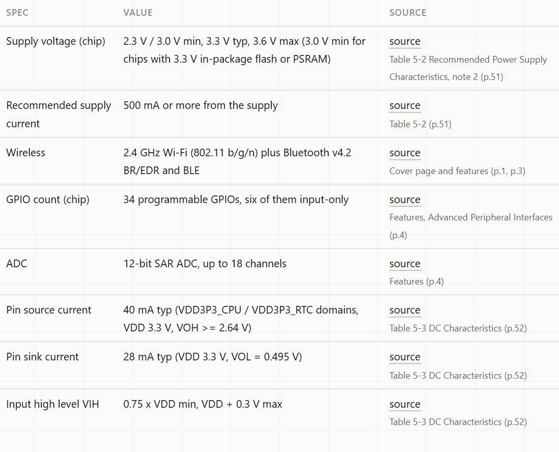
So the rule is one-directional. 5 V into an ESP32 pin is outside the rating. 3.3 V out of an ESP32 pin is fine for the ESP32, and the question is only whether the part on the other end sees it as high.
Case 1: the sensor sends 5 V to the ESP32
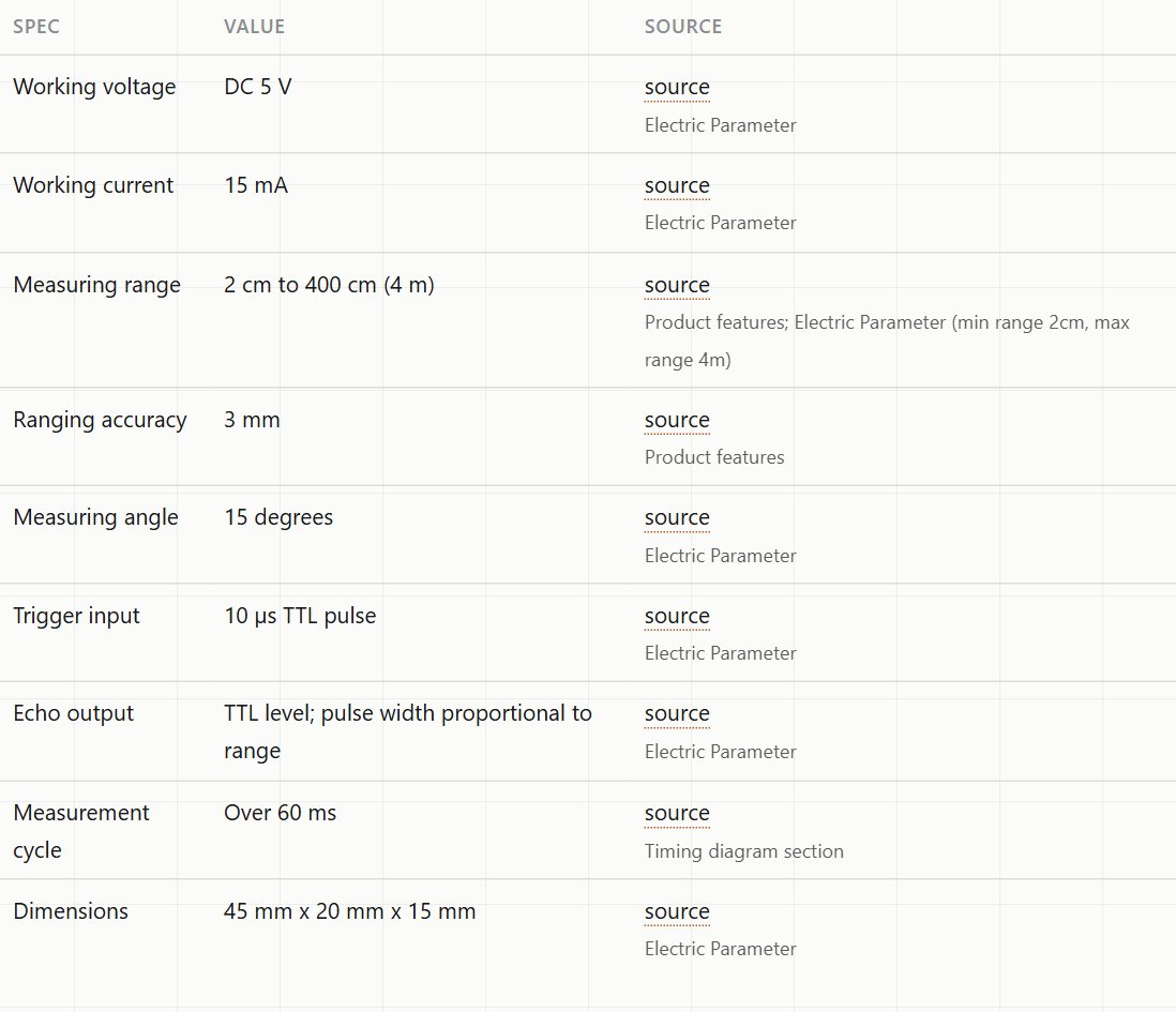
The classic example is the HC-SR04 ultrasonic sensor. Its datasheet gives a 5 V working voltage and a TTL-level echo output, so the echo pin swings up to about 5 V.
Two ways to bring it down:
- A voltage divider. Two resistors from the echo pin to ground, with the ESP32 input at the middle. A 1 kΩ resistor on top and a 2 kΩ resistor below gives 5 V × 2 / 3 ≈ 3.3 V. It takes two resistors and works for one-way signals that aren't very fast.
- A level shifter module. Better for several signals, faster signals, or anything bidirectional.
The trigger pin goes the other way (ESP32 to sensor) and is a TTL input, which normally accepts 3.3 V as high. Check the threshold in your sensor's datasheet if you're unsure.
Case 2: the ESP32 sends 3.3 V to a 5 V part
This direction doesn't harm the ESP32. Whether it works depends on the receiving part's input threshold. Many 5 V modules accept 3.3 V as high; some don't, especially ones with CMOS inputs that want a high level close to their own supply. If a 5 V module ignores the ESP32's signal, a level shifter fixes it.
Relay boards deserve a note of their own. A 5 V relay module driven from a 3.3 V pin may or may not switch, depending on the driver circuit on the board. Use a module stated to trigger from 3.3 V, or drive it through a transistor.
Case 3: I2C modules, where the pull-ups decide
I2C lines are pulled up to a voltage by resistors, usually on the module. If a module powered from 5 V has pull-ups to 5 V, the ESP32's SDA and SCL pins sit at 5 V between messages, outside the rating, even though the sensor chip on the module might be a 3.3 V part.
Two things help:
- Power 3.3 V-capable modules from the ESP32's 3.3 V pin. Their pull-ups then go to 3.3 V. Many sensor chips are 3.3 V parts anyway: the BME280 chip is rated 1.71 to 3.6 V, even when the module listing says 5 V.
- Use an I2C level shifter for modules that genuinely need 5 V. I2C is bidirectional, so a simple divider won't do.
Module boards are where the datasheets go quiet. The chip's datasheet gives the chip's limits; the regulator, pull-ups and header on the module usually aren't in any official document. Our reference pages say so explicitly, under Not covered by the official source, so you know which details to check on your own board.
How Soldr handles it
When Soldr picks parts for an ESP32 build, it flags logic-level mismatches under Common problems. For a touch-pad game with a TTP226 touch module, the code it wrote chose to power the module from 3.3 V and said why: "The TTP226 is powered from 3V3 so its outputs stay at 3.3V logic." That one decision removes the mismatch instead of adding a level shifter.
If you already know a part's logic level, put it in the prompt ("a 5 V HC-SR04 with a divider on the echo pin"), so the build can account for it instead of guessing. More prompt tips in how to describe a hardware build to an AI.
Quick checklist
- List every signal between the ESP32 and a 5 V part, and its direction.
- 5 V into the ESP32: divider or level shifter.
- 3.3 V out to a 5 V part: check its input threshold; shift it if needed.
- I2C: find where the pull-ups go. Prefer 3.3 V power for modules that allow it.
- Never feed 5 V into the ESP32 module's 3.3 V supply pin. Its range is 3.0 to 3.6 V.
Parts from this post on Compoden: HC-SR04 ultrasonic sensor, ESP32-DevKitC, TTP226 touch module. Choosing between the ESP32 and a 5 V Uno in the first place? Read ESP32 vs Arduino Uno.
Describe your build on app.soldr.ai. Sign in and get 100 credits free.