8 November 2026 · Soldr
MPU6050 not found at 0x68? A checklist that finds it
Short answer: run an I2C scanner first. If it finds the sensor at 0x69, the AD0 pin is high; change the address in your code or tie AD0 low. If it finds nothing, check SDA and SCL, ground, and power (the chip itself is a 2.375 to 3.46 V part, so a 5 V module relies on its own regulator). If something else answers at 0x68, such as a DS3231 clock, you have an address clash.
"MPU6050 not found" or "Failed to find MPU6050 chip" is one of the most common first errors with motion sensors. The fix is almost always on the bench, not in the code. The facts below come from the MPU-6050 datasheet, as cited on our MPU6050 reference page.
Step 1: what does the scanner see?
An I2C scanner tries every address and prints the ones that answer. There's a short one in our post on I2C address conflicts. The result tells you which branch you're on:
- Found at 0x68: the sensor is fine and wired. The problem is in the code: wrong address, wrong I2C pins passed to the library, or another device also at 0x68 (step 4).
- Found at 0x69: AD0 is high (step 2).
- Nothing found: wiring or power (step 3).
Step 2: the AD0 pin
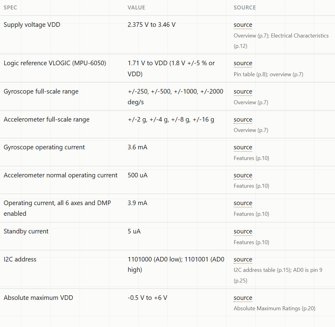
The datasheet gives the address as 1101000 with AD0 low and 1101001 with AD0 high: 0x68 or 0x69. Leaving AD0 unconnected, or guessing its level, is a common mistake our reference page flags: the wrong level hides the device at the address you expect. On many breakout modules AD0 is brought out to a header pin. Tie it to GND for 0x68, or to the logic supply for 0x69, and use the same address in your code.
Step 3: nothing answers
- SDA and SCL. On an Uno they're A4 (SDA) and A5 (SCL). On an ESP32 DevKit the usual pins are GPIO21 (SDA) and GPIO22 (SCL), but your code decides. If it calls
Wire.begin()with other pins, wire to those. Swapped SDA and SCL is the classic mistake. - Ground. The module and the board must share ground.
- Power. The MPU-6050 chip's supply range is 2.375 to 3.46 V (absolute maximum 6 V). Modules sold for "3 to 5 V" carry a regulator that no official document describes. On a 3.3 V board like the ESP32, power the module from 3.3 V. On a 5 V Uno, use the module's VCC input as its label says.
- Logic level. The datasheet gives no 5 V tolerance for SDA and SCL: their absolute maximum is VDD + 0.5 V. Whether a given module protects them isn't documented, which is another reason to keep the I2C bus at 3.3 V where you can.
- Pull-ups. I2C needs pull-up resistors on SDA and SCL. Most breakout modules include them. A bare chip, or a long cable, may need your own.
Step 4: two devices at 0x68
The DS3231 real-time clock also uses 0x68, and has no way to change it. With both on one bus, neither works reliably. The fix is on the MPU6050's side: tie AD0 high so it moves to 0x69, and update your code. Our address conflict post lists the addresses of other common I2C parts.
Step 5: found, but readings look wrong
If the sensor is found but the numbers make no sense, check the basics in the sketch's first reading. Many libraries report acceleration in m/s². With the module lying flat, one axis should read about 9.8 and the other two near zero. All zeros usually means the sensor is answering but wasn't woken or configured, which is a code issue. Wildly jumping values usually mean loose wires.
How Soldr handles it
When we built a motion-reactive desk toy on Soldr without giving any addresses, Soldr flagged it in its reply: "Fix this first: I could not verify the OLED and MPU6050 I2C addresses". With the address in the prompt ("an MPU6050 at I2C address 0x68"), the sketch it wrote checks for the sensor at startup. If the sensor isn't there, the Serial Monitor shows:
[INIT] MPU6050: FAIL (no response at 0x68)
[FIX] MPU6050: check SDA/SCL wiring, 3V3 power, and that AD0 is low (0x68); eyes will idle-wander instead
That's this checklist in two lines. More on reading self-test lines.
On Compoden: MPU6050 module, DS3231 RTC. Describe your build on app.soldr.ai. Sign in and get 100 credits free.