8 November 2026 · Soldr
I2C LCD address 0x27 or 0x3F? Fixing a blank 16x2 LCD
Short answer: a 16x2 or 20x4 LCD with an I2C backpack answers at the address of the expander chip on the back. A PCF8574 answers somewhere from 0x20 to 0x27 (0x27 with all address pins high). Backpacks built on the PCF8574A variant use a different range, often 0x3F. Run an I2C scanner, use the address it prints, then turn the contrast trimmer. Those two steps fix most blank LCDs.
The I2C backpack is a small board soldered to the back of a character LCD. It turns the display's dozen parallel wires into two signal wires plus power, using an 8-bit I2C expander chip. It's a great part. It's also behind a large share of "my LCD lights up but shows nothing" problems. Here's what the datasheet says and how to work through it.
Where the address comes from
From the PCF8574 datasheet, as cited on our PCF8574 backpack and 16x2 I2C LCD pages:
- The 7-bit address is
0100 A2 A1 A0. The last three bits come from the chip's A2, A1 and A0 pins. That gives 0x20 to 0x27. - With all three pins pulled high, the address is 0x27, the value many tutorials hard-code.
- The address pins must be tied to VCC or ground. On most backpacks that's done with pull-up resistors and solder jumpers marked A0, A1 and A2; the backpack board itself isn't covered by the chip's datasheet, so check yours.
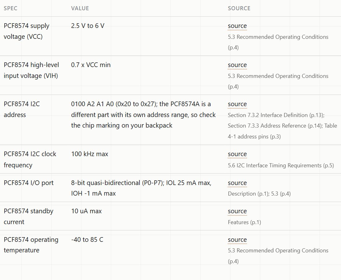
The PCF8574A is a near-twin chip with a different fixed part of the address, so a backpack built on it answers in a different range. The PCF8574 datasheet doesn't cover the A variant, so read the marking on your backpack's chip. In practice, backpacks that don't answer at 0x27 very often answer at 0x3F.
Step 1: find the real address
Don't guess between 0x27 and 0x3F. Run an I2C scanner, which tries every address and prints the ones that reply. There's a short one in our post on I2C address conflicts. Then put that address in your code.
- Scanner finds nothing? Check SDA and SCL (on an Uno they're A4 and A5; on an ESP32 DevKit usually GPIO21 and GPIO22), ground, and power to the backpack.
- Scanner finds two devices you didn't expect? Something else on the bus may share the range. Compare the addresses with your parts list.
Step 2: turn the contrast trimmer
The small blue potentiometer on the backpack sets the LCD contrast. Out of the box it's often turned so far that the text is invisible, or so far the other way that you see a row of solid blocks. With the sketch running, turn it slowly until the characters appear. A row of solid blocks with nothing else usually means the display has power but hasn't been initialised: check the address in the code.
Step 3: check the logic level (ESP32 and other 3.3 V boards)
This one catches ESP32 users. The PCF8574 datasheet gives its input-high threshold as 0.7 × VCC. If the backpack is powered from 5 V, that's 3.5 V. A 3.3 V board's high signal sits below it. It may work on your bench and fail on someone else's.
The chip itself runs from 2.5 to 6 V, so you have options:
- Use an I2C level shifter between a 3.3 V board and a 5 V backpack.
- Or power the backpack from 3.3 V, if your LCD panel works at 3.3 V. Many character LCDs are sold as 5 V panels and look faint or blank at 3.3 V, so test yours.
- Or use a 5 V board such as an Uno, where everything matches.
There's more on mixing 5 V and 3.3 V parts in 5 V sensors on a 3.3 V ESP32.
Step 4: keep the bus at 100 kHz
The PCF8574 datasheet gives 100 kHz as its maximum I2C clock. If you've sped up the bus for another device, the backpack may drop out. Leave the bus at the default 100 kHz when an LCD backpack is on it.
Checklist for a blank I2C LCD
- Scanner: does the backpack answer, and at what address?
- Code: does it use that address?
- Contrast: turn the trimmer with the sketch running.
- Logic level: 3.3 V board with a 5 V backpack? Add a level shifter.
- Clock: is the bus at 100 kHz?
- Backlight: is the backlight jumper fitted on the backpack?
On Compoden: the 16x2 I2C LCD and 20x4 I2C LCD with the backpack pre-soldered, and the PCF8574 backpack on its own.
When you build with one of these on Soldr, say the address if you've scanned it ("a 16x2 I2C LCD at 0x27") so the build doesn't have to guess. Describe your project on app.soldr.ai. Sign in and get 100 credits free.