23 August 2026 · Bharat Raj · originally published on Compoden
PWM Explained: How One Digital Pin Fakes an Analog Voltage

PWM (pulse-width modulation) fakes an analog voltage by switching a digital pin fully ON and fully OFF very fast, so the average voltage the load experiences depends on what fraction of each cycle the pin spends ON. A pin that is ON 25% of the time and OFF 75% of the time delivers an average of 25% of the supply voltage: about 1.25V from a 5V Arduino Uno R3 pin. The fraction is called the duty cycle, and the switching happens hundreds or thousands of times per second, far too fast for an LED's apparent brightness or a motor's speed to follow the individual pulses. The load responds to the average, and you get smooth dimming and speed control from a pin that only knows HIGH and LOW.
The problem PWM solves
Digital pins are switches, not taps. They can output 5V or 0V, nothing in between. But the physical world is full of in-betweens: half-bright LEDs, slow-spinning fans, warm-not-hot heaters. Producing a genuine intermediate voltage takes a DAC (digital-to-analog converter), and most hobby microcontrollers have few or none. Worse, a true analog output wastes power: to give a motor 2.5V from a 5V supply through a linear circuit, something must burn off the other 2.5V as heat.
PWM sidesteps both problems. The transistor driving the pin is always either fully on (almost no voltage across it) or fully off (almost no current through it), and in both states it dissipates nearly nothing. That efficiency is why PWM runs everything from phone screen brightness to electric vehicle motors.
Duty cycle and frequency
Two numbers define a PWM signal. The duty cycle is the ON percentage: 0% is always off, 100% is always on, 50% is a square wave. The frequency is how many ON-OFF cycles happen per second. On the Uno, analogWrite(pin, value) takes a value from 0 to 255, mapping to 0% to 100% duty. analogWrite(9, 64) gives roughly 25% duty.
Frequency matters less than beginners expect, until it suddenly matters a lot. The Uno's default is about 490Hz on most PWM pins and 980Hz on pins 5 and 6. For LEDs, anything above roughly 100Hz looks steady to the eye. Motors are happier at higher frequencies, and audible whine appears when the PWM frequency sits in the hearing range, which is exactly where 490Hz lives. That faint singing from a PWM-driven motor is the windings vibrating at the switching frequency.
Where the smoothing happens
Here is the subtle part: the pin never outputs 1.25V. Put an oscilloscope on it and you see crisp 5V pulses. The averaging happens in the load. An LED plus your eye average by persistence of vision. A motor averages mechanically, because its rotor is too heavy to speed up and slow down 490 times a second, and electrically, because its winding inductance smooths the current. If you truly need a steady analog voltage, say to feed an analog input on another device, you add a low-pass filter: a resistor and capacitor (10kΩ and 10µF is a fine start) that charge to the average and hold it there, with a little ripple.
Worked example: dimming an LED on an Arduino Uno R3
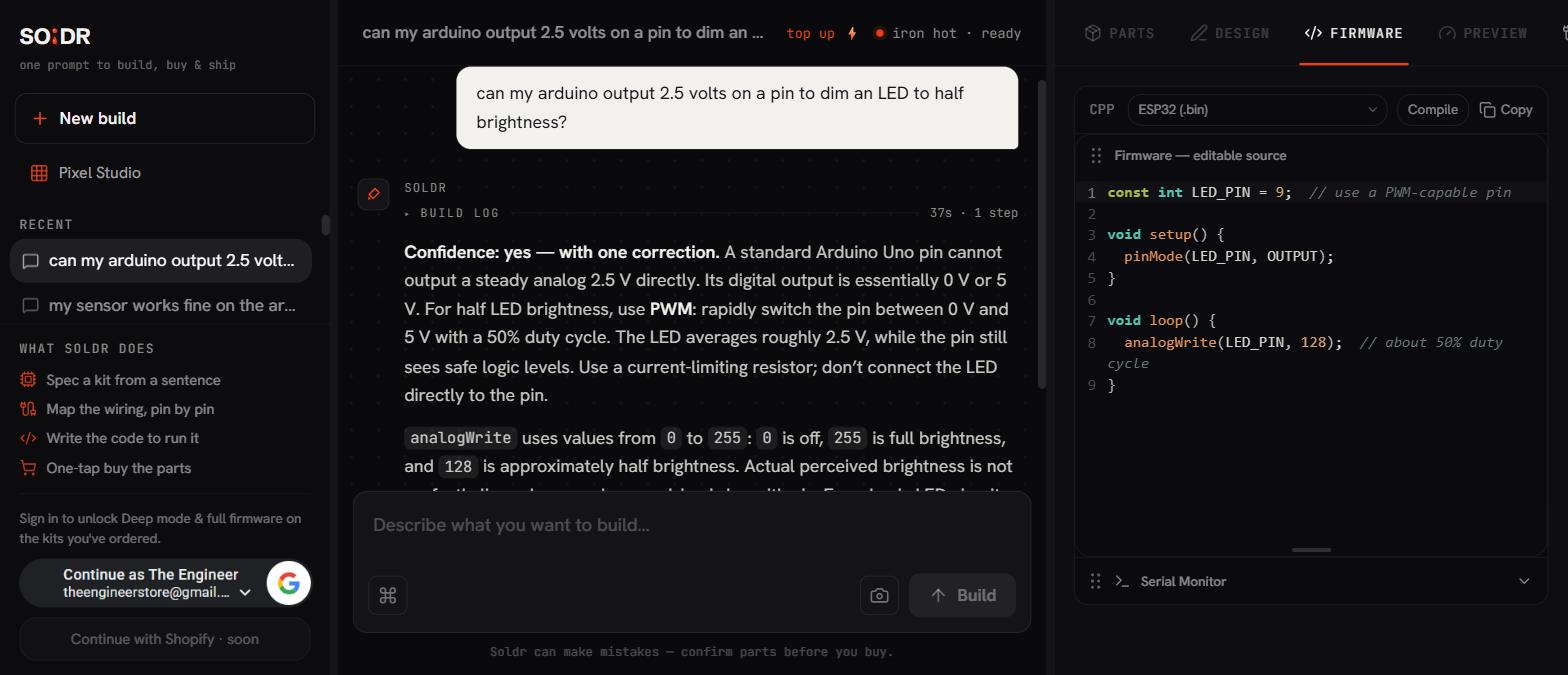
Take a 5mm LED, a 330Ω resistor from a resistor variety pack, and a 400-point breadboard. Wire pin 9 (a PWM pin, marked with ~ on the board) through the resistor to the LED anode (long leg), and the cathode to GND with a Dupont jumper wire.
In code, loop analogWrite(9, b) with b ramping 0 to 255 and back, with a small delay. The LED breathes smoothly. Now try the same with digitalWrite and you get only on or off; that is the entire difference PWM makes. One instructive experiment: set analogWrite(9, 10) and wave the board around in a dark room. You will see a dotted trail instead of a streak, which is the pulsing made visible.
Where this bites you
The first trap is expecting a real voltage. Beginners measure a PWM pin with a multimeter, see about 2.5V at 50% duty, and conclude the pin outputs 2.5V. The meter is averaging. Feed that same pin to something that responds fast, like another chip's digital input or a MOSFET gate, and it sees full-speed 5V pulses, not a mid-level voltage. Whether that is fine or a bug depends entirely on the load.
The second trap is the servo confusion. An SG90 servo is controlled by pulse width, but not by analogWrite PWM. Servos want a pulse of 1 to 2 milliseconds repeating every 20 milliseconds; the pulse duration, not the duty percentage, encodes the angle. Use the Servo library, which generates the correct timing, and do not point analogWrite at a servo and expect sensible motion.
Third: only the pins marked ~ (3, 5, 6, 9, 10, 11 on the Uno) support hardware PWM. Call analogWrite on pin 7 and you silently get all-or-nothing output. No error, just wrong behaviour.
FAQ
Why does my PWM-dimmed LED flicker on camera but look fine to my eye?
Cameras sample the scene at a shutter speed that can beat against the PWM frequency, producing visible banding or flicker. Your eye averages over a longer window. It is an artefact of the interaction, not a fault in your circuit.
Can I drive a motor directly from a PWM pin?
No. An Uno pin supplies about 20mA safely (40mA absolute maximum), while even a small DC motor wants hundreds of milliamps. The PWM signal goes to a transistor, MOSFET, or a driver board like the L298N motor driver, which does the heavy switching and passes the duty cycle through to the motor.
Is analogWrite the same as analogRead?
They are unrelated despite the names. analogRead uses a real ADC to measure a voltage on pins A0 to A5. analogWrite produces PWM on the ~ pins. There is no true analog output on the Uno at all.
When you want PWM doing real work, dimming, fans, motor speed, Compoden's AI build assistant Soldr can wire the driver stage into your project and generate the matching code.