23 August 2026 · Bharat Raj · originally published on Compoden
How Relays Actually Work: Coil, Contacts, and the Click

A relay is an electrically operated mechanical switch: current through a coil creates a magnetic field that physically pulls a metal armature, which snaps a set of contacts together or apart, letting a small low-voltage circuit switch a completely separate high-power circuit. The click you hear is that armature moving. Because the coil circuit and the contact circuit are electrically isolated from each other, a 5V microcontroller can safely switch a 230V mains appliance without the two circuits ever touching. That isolation is the relay's superpower, and understanding the coil side, the contact side, and the boundary between them is most of what you need to use relays safely.
The coil side: an electromagnet
Inside the relay, a coil of fine wire wraps around an iron core. Push current through it (a typical 5V hobby relay coil draws 70 to 80mA) and the core becomes a magnet, attracting a hinged iron armature against spring tension. Cut the current and the spring snaps the armature back. That is the entire actuation mechanism: an electromagnet and a spring fighting over a lever.
Two consequences follow. First, 70mA is beyond what an Arduino Uno R3 pin should supply, so a bare relay needs a driver transistor between the pin and the coil. Second, the coil is an inductor, and interrupting an inductor's current creates a nasty voltage spike, so the coil needs a flyback diode across it. Relay modules, the little boards with the blue relay on top, include both, plus often an optocoupler for extra isolation, which is why modules are the sensible choice for beginners.
The contact side: COM, NO, and NC
The switched side presents three terminals. COM (common) is the moving contact. NO (normally open) is disconnected from COM until the coil energises. NC (normally closed) is connected to COM until the coil energises. "Normally" means coil off.
Wire your load between the supply and COM-to-NO if it should be off by default and turn on when commanded: the usual choice, and the safe one, because a crashed or unpowered controller leaves the load off. Use NC for loads that must default to on, such as a fail-safe cooling fan. The contacts carry a rating printed on the relay, commonly 10A at 250VAC or 10A at 30VDC. Those are maximums for a resistive load; motors and other inductive loads should be derated to roughly half.
Isolation: the boundary that keeps you safe
Nothing electrical connects the coil circuit to the contact circuit. The only link is magnetic force across an air gap. This is galvanic isolation, and it is why relays remain everywhere despite being mechanical, slow (about 10ms to switch), and mortal (contacts erode over tens of thousands of operations). When the switched circuit is 230V mains, isolation is not a nicety. It is the design. Keep mains wiring physically away from your low-voltage side, use insulated terminals, and never prototype mains connections on a 400-point breadboard; breadboards are neither rated nor spaced for mains voltages.
Worked example: Uno plus a relay module driving a lamp
Take a common single-channel 5V relay module. Three input pins: VCC to the Uno's 5V, GND to GND, IN to digital pin 7, all with Dupont jumper wires. The module's transistor, flyback diode, and indicator LED are already on the board.
Many of these modules are active-low: pulling IN to ground energises the relay, so digitalWrite(7, LOW) switches on and HIGH switches off. Test yours with a multimeter in continuity mode across COM and NO before wiring any load: beep means closed. For the load side, have a qualified person wire the lamp's live wire through COM and NO if you are switching mains; for a first project, switch a 12V DC lamp or fan instead and keep every part of the learning loop at safe voltages.
Where this bites you
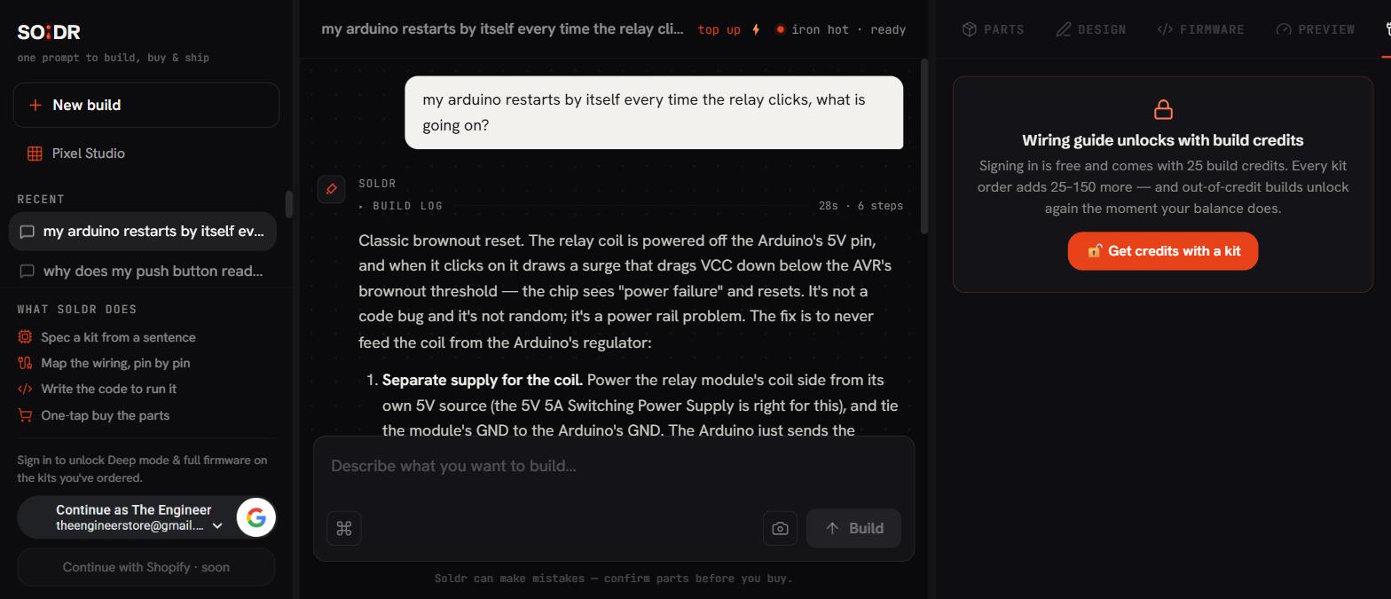
The most common failure: powering the relay coil from the Uno's 5V pin along with everything else, then watching the board reset every time the relay clicks. The coil's 70mA plus its switching transient sags the rail, especially when the Uno itself runs from a weak USB port. Give relay modules their own 5V supply where possible, joined to the Uno by ground, or at minimum add a bulk capacitor across the rail.
Second: misreading active-low modules. The sketch says HIGH for on, the module says LOW for on, and the lamp behaves exactly backwards, including switching on when the board resets. Establish the module's polarity first, then write the code.
Third: trusting the relay to switch a motor at its full printed rating. Contacts that switch 10A resistive will pit and weld far sooner switching an inductive load that arcs on every disconnect. Derate, and for frequent switching of motors, consider a MOSFET (for DC) or a solid-state relay (for AC) instead.
FAQ
Why does my relay chatter (click rapidly on and off)?
Chatter means the coil voltage is dipping below the hold-in threshold and recovering, over and over. Usual causes: an undersized supply sagging under coil current, thin jumper wires dropping voltage, or the driving pin browning out. Give the coil a solid supply and the chatter stops.
Relay module or bare relay: which should I buy?
A module, almost always. The bare relay needs a transistor, base resistor, and flyback diode around it before it is usable from a microcontroller. The module includes them for nearly the same money and adds screw terminals and status LEDs. Bare relays make sense inside finished PCB designs.
Can a relay switch signals as well as power?
Yes, and small signal relays exist specifically for it, but ordinary power relay contacts are not great for tiny signals: the contact surfaces need a minimum wetting current to stay clean. For routing audio or logic signals, use a signal relay or an analog switch IC instead of a 10A power relay.
When your project graduates from LEDs to switching real appliances, Compoden's AI build assistant Soldr can plan the relay stage and its wiring into your build the safe way.