23 August 2026 · Bharat Raj · originally published on Compoden
Common Ground: Why Two Powered Circuits Ignore Each Other
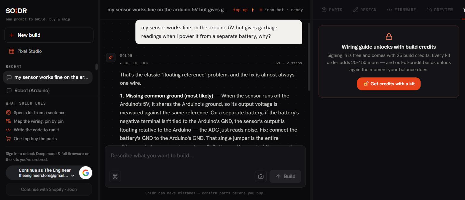
Two circuits can only understand each other's signals if their grounds are connected, because every voltage is a difference between two points, and without a shared ground the two circuits have no common reference to measure that difference against. A signal wire from an Arduino to a motor driver does not carry "5V" in any absolute sense; it carries "5V above my ground". If the driver's ground floats somewhere else entirely, the driver reads gibberish, or nothing. This is the single most common wiring omission in multi-supply projects: the battery-powered motor board and the USB-powered Arduino each work perfectly alone, and the connection between them does nothing, because nobody ran the one humble wire joining GND to GND.
Voltage is always a difference
There is no such thing as the voltage of a single point, only the voltage between two points, the way there is no such thing as the height of a mountain without saying "above sea level". Electronics borrows the same trick: each circuit picks one node, calls it ground (0V), and states every other voltage relative to it. Ground here means reference node; it need not touch the actual earth. A battery-powered toy has a ground with no connection to the planet whatsoever.
The catch is that each isolated circuit picks its own sea level. Your Arduino Uno R3's ground is the negative side of its USB supply. A motor's battery pack has its own negative terminal as its own private zero. Between two unconnected circuits, the difference between the two grounds is undefined; it can float to any value, drift with static, and hum with coupled 50Hz noise from the 230V mains wiring around you. A signal referenced to one floating level, read against another floating level, means nothing.
The fix is one wire
Connect the grounds and both circuits agree on zero. Now "5V above my ground" from the sender is "5V above our ground" for the receiver, and the signal carries meaning. That is the whole rule: every pair of circuits that exchange signals must share a ground connection. Separate positive rails are perfectly fine and often desirable, the Uno on USB 5V, the motors on a 7.4V pack, but the grounds join.
This is so fundamental that experienced makers wire ground first, and when anything intermittent or inexplicable happens between two boards, they check ground continuity before anything else. A multimeter in continuity mode, black probe on one board's GND pin, red on the other's: a beep says the reference is shared.
When grounds must NOT simply be joined
The rule has boundaries worth knowing early. Circuits are sometimes isolated on purpose: a relay's contact side, an optocoupler's output side, and anything involving mains exist precisely to keep two domains electrically separated, and bridging their grounds defeats the safety. Never tie your low-voltage ground into anything on the mains side of a relay or the earth pin of a socket. Also, when two grounds do carry heavy current, how you join them matters: motor current flowing through a shared ground wire drops millivolts along it, which the sensitive side reads as noise. The practical hobby answer is star grounding, joining each board's ground to one common point rather than daisy-chaining, with fat, short wires for the high-current paths.
Worked example: Uno, L298N, and a battery
The textbook case, because it fails in real projects weekly. An L298N motor driver runs two DC motors from a 7.4V battery pack. The Uno runs from USB. Control wires go from Uno pins to the driver's IN1 through IN4 with Dupont jumper wires.
Wired exactly like that, with battery to the driver's power terminals and signals connected, the motors do nothing, or twitch randomly. Both boards' power LEDs glow; everything looks alive. The missing piece is one jumper from the Uno's GND to the L298N's GND terminal. Add it and the IN pins finally see clean logic levels relative to the driver's own reference, and the motors obey. Three supplies or two, the principle scales: all grounds meet, positive rails stay separate unless you deliberately share one. (A 400-point breadboard's blue rail makes a convenient meeting point for the ground wires.)
Where this bites you
The missing ground produces the strangest symptom profile in hobby electronics, which is why it eats so much debugging time. Signals sometimes get through, because parallel paths, a shared USB hub, a programmer cable, capacitive coupling, provide a ghostly partial reference. So the servo jitters instead of failing, the sensor reads plausible-but-wrong values, the serial link works until you unplug an unrelated cable. Anything that half-works between two separately powered boards should trigger the same reflex: beep the grounds.
The second bite is subtler: ground offset. The grounds are connected, but through a long thin wire also carrying an SG90 servo's current spikes. Each spike drops voltage along that wire, so the two boards' zeros bounce apart by tens or hundreds of millivolts, corrupting analog readings in rhythm with the servo. The giveaway is noise that correlates with mechanical activity. The fix is thicker, shorter ground wiring and separate ground paths for power and signal, meeting at one point.
FAQ
Do two boards powered from the same USB hub or power bank already share ground?
Usually yes, through the supply's negative rail, which is why some missing-ground wiring appears to work in one setup and fails when you switch to batteries. Do not rely on the accident: run the explicit ground wire anyway, so the circuit works because of its wiring rather than despite it.
Is "ground" the same as the earth pin in a wall socket?
No. Circuit ground is a reference node chosen by the design; protective earth is a safety conductor tied to the physical ground to trip breakers during faults in mains appliances. They coincide inside some mains-powered equipment, but your battery and USB projects never need, and should not touch, the socket's earth pin.
Can connecting grounds ever cause damage?
Between two low-voltage, isolated hobby supplies, joining grounds is safe. Trouble arrives when one "ground" is not a true isolated reference, for example anything on the mains side of a relay, some non-isolated mains LED drivers, or two mains-powered devices whose grounds sit at different potentials. Keep mains domains isolated and the rule "grounds together" stays safe everywhere else.
Wire a multi-supply project with Compoden's AI build assistant Soldr and the ground connections are placed in the plan first, before the interesting wires.