8 November 2026 · Soldr
A4988 and DRV8825 current limit: setting Vref the right way
Short answer: the current limit is set by the voltage on the driver's reference pin and the value of its sense resistors. A4988: ITripMAX = VREF ÷ (8 × RS). DRV8825: ICHOP = VREF ÷ (5 × RSENSE). Read RS from your own board, pick a current at or below your motor's rated phase current, work out VREF, then turn the trimmer while measuring it with a multimeter.
A stepper driver with no current limit set is the fastest way to a hot motor, a hot driver, or skipped steps. Both of the common modules let you set the limit with a tiny potentiometer, but the formula and the sense resistor differ between them and between boards. Here's how to get it right from the datasheets, as cited on our A4988 and DRV8825 reference pages.
The two formulas
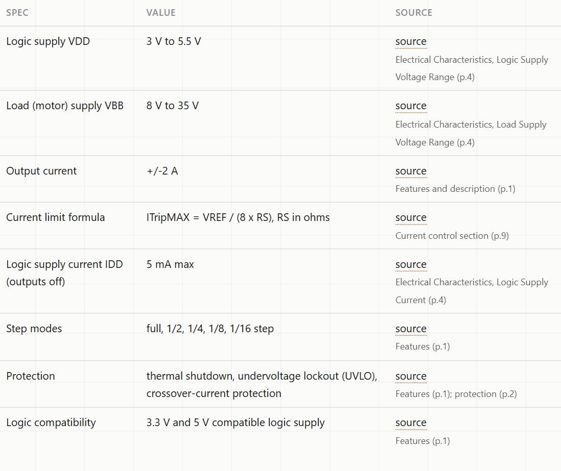
A4988 (Allegro datasheet, current control section)
ITripMAX = VREF ÷ (8 × RS), with RS in ohms. So VREF = I × 8 × RS.
DRV8825 (TI datasheet, current regulation, equation 1)
ICHOP = VREF ÷ (5 × RSENSE). So VREF = I × 5 × RSENSE. The datasheet's own example: a 0.25 Ω sense resistor and 2.5 V on VREF give 2 A.
Step 1: find your sense resistor value
This is where most guides go wrong, because the value is on the module, not in the chip datasheet. Both of our reference pages list it under Not covered by the official source. Look for two small resistors near the chip, usually marked with a code such as R100 (0.100 Ω) or R050 (0.050 Ω). Use that value in the formula, not one from a tutorial for a different board.
Step 2: choose the current
Use your motor's rated phase current from its label or datasheet, and set the limit at or below it. Going lower runs the motor and driver cooler at the cost of some torque. Also respect the driver's own limit: ±2 A for the A4988, and 2.5 A per output for the DRV8825 with proper heat sinking, at 24 V and 25 °C.
Step 3: work out VREF
Two worked examples, assuming a 1.0 A target:
- A4988 with RS = 0.100 Ω: VREF = 1.0 × 8 × 0.100 = 0.80 V.
- DRV8825 with RSENSE = 0.100 Ω: VREF = 1.0 × 5 × 0.100 = 0.50 V.
Same motor, same current, different voltage, because the formulas differ. Mixing them up gives you the wrong current.
Step 4: measure while you turn
- Power the driver's logic (and, on most modules, the motor supply too, which the trimmer circuit may depend on). Keep the motor wires secure and don't let them come loose while powered.
- Put the multimeter's black probe on ground and the red probe on the reference point: the A4988's REF pin, or the DRV8825's VREF, often the trimmer's metal top on common modules.
- Turn the trimmer slowly with a ceramic or plastic screwdriver until the meter reads your target.
- Run the motor and feel the driver and the motor after a few minutes. Warm is normal. Too hot to touch means the limit is too high or the cooling is too weak.
Other things the datasheets warn about
- Motor supply range. A4988: 8 to 35 V. DRV8825: 8.2 to 45 V. Below the minimum, the driver won't run properly.
- Decoupling. The A4988's typical application shows 100 µF near the motor supply. TI asks for 0.1 µF bypass plus bulk capacitance on the DRV8825's VM pins, both on the same supply.
- DRV8825 nSLEEP and nRESET. Both must be high to operate, and both have internal pull-downs. Leave them floating and the chip stays asleep or in reset. After waking, wait about 1 ms before the first step.
- Logic levels. The A4988's logic supply is 3 to 5.5 V, so match it to your board. The DRV8825 treats 2.2 V and above as high, so both 3.3 V and 5 V boards can drive it.
- Heat. Both chips shut down if they overheat. The DRV8825's full current needs heat sinking.
With a CNC shield or a Pi HAT
The same formulas apply when the drivers plug into a CNC Shield V3: set each driver separately. Ready-made boards like the Elecrow stepper motor HAT (dual A4988, I2C 0x6F, 5 to 12 V motor supply) set their current their own way; check the board's documentation before you adjust anything.
When you describe a stepper build on Soldr, include the motor's rated current ("a NEMA 17 rated 1.5 A per phase"). The build can then size the motor supply, and you set VREF with the formula above.
On Compoden: A4988 driver, DRV8825 driver, CNC Shield V3. Describe your build on app.soldr.ai. Sign in and get 100 credits free.